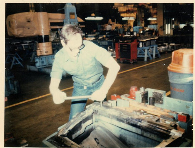
Mark Corbin working in the GM plant (photo courtesy of Mark Corbin)
Part 1, by Mark Corbin
How does flat sheet steel get made into a car’s fender, door, or flooring? There is more to it than most people realize. Ever try to bend a piece of sheet metal? Now multiply the force it took for you to merely bend it. Now imagine a hammer hitting the sheet metal hard enough to form a dent in the metal. Then imagine a press capable of actually putting a permanent form into that sheet of metal. Such presses are identified by the amount of pressure they can put on the panel, and can range from 50 tons to as high as 200 tons, or more. The tooling that forms the shapes of car parts are called dies, and usually are at least half again the size of the part. The dies form, trim, punch holes, and fold over that piece of flat metal into the finished parts, and it can take as many as eight dies in a line to make a single quarter panel, start to finish.
On conventional cars, Fisher Body was responsible for everything but the front clip. Unitized cars like the Corvair were “horse traded” with a mixture of other jobs with the division getting the body. This was the case from the early teens when GM was put together up until the mid 1980’s when Roger Smith dismantled the corporation and reorganized it. So all of the Corvair body was Fisher’s responsibility. Check the “body on a pallet” for what Fisher did. It’s now in our museum in Illinois.
Some of the sheet metal was stamped at other stamping plants like at a plant like mine. There are other stamping plants around the country that did what we did. Grand Blanc, Flint, and Indianapolis seem to come to my mind. We just turned coil flat steel into finished individual parts and did some sub-assemblies. If any Corvair metal was stamped at my plant, I don’t know. It was before my hiring on there.
There’s not too many shots of inside the plant in existence as that is against company policy. The one I have is mostly a fluke. Picture taking has to be approved by management.
I worked for 30 years at the Mansfield/Ontario Ohio plant of Fisher Body/General Motors, so I know about sheet metal forming. I hired into the plant as an apprentice diemaker, and after about 4 years of on-the-job training, I earned my journeyman’s papers. That skilled trade is where the tools that make sheet metal parts are built and maintained. Much of the work involves heavy metal parts that are precision-made to exacting standards. If two mated parts of a trim die, for example, are not spaced right, the part doesn’t get trimmed right. Too tight or too loose can create burrs and sharp edges, deformed holes, or even fail to trim a part as required. And tolerances are measured in thousands of an inch.
The first die in a line is the draw die. It puts the initial shape and form of the part into the flat panel. Any area on the panel that is convex or has a character line needs to have both die halves mate together exactly when the die bottoms out in the press. It is why dies often require weeks of around-the-clock grinding in order to get those surfaces to fit together down to zero open areas. Plus the finished surface of the punch must be polished to a mirror finish.

In the auto industry, the draw die (with some exceptions) is usually constructed of three pieces, the punch and the binder ring, mounted on the upper rams of the press; and the female, mounted on the lower press bed. If a two-ram press is not available, the die can be built upside down, with the binder ring supported by a bed of air cylinders containing a charge of nitrogen under pressure. It’s the amount of force of this pressure, determined by the height of the rams and/or the nitrogen charge on the binder part of the die that creates the power to form the part correctly. Too high a pressure, and the part may (and usually does) split. Too little pressure and the metal will flow in too fast and bunch up into what is called double metal.
For example, if you look at the factory-made trunk floor in a Late Model, it has a very deep draw with the trunk bottom having rounded corners in what I call “three sides of a box”. That is where you could get the metal bunching up if it wasn’t for the binder ring holding the metal back and forcing it to stretch and flow around its designated form. But note the Clark’s replacement panel has what looks like a slot in each corner. That’s because they are using a crash die and a blank shaped like a four-leaf clover. It’s less expensive tooling, but it has a problem. Since a crash die doesn’t have a binder ring, the panel simply wraps up around the punch as the die closes. If it was an uncut sheet, it would bunch up in the corners, hence the need to cut the corners out so that there is no excess metal to bunch up. The factory metal panel is much larger and contains more of the trunk area, thus it requires the stretch to form it all.
Also, consider Clark’s reproduced windshield frame panel, the panel used along the bottom of the windshield that always is a problem on Late Models. There is no doubt in my mind that it is stamped in a crash die that is probably machined to match the contour of the factory part. The problem is that in order to best hold its shape, metal must be stretched past its yield point. If it doesn’t stretch past there, it tends to want to spring back like a rubber band. The result is a part that doesn’t quite match the contour of the original factory part. This is where a checking fixture comes into play. If the company making this part had only checked the parts with a checking fixture made to precisely match an original panel, the die would have had to be remachined and reworked so as to allow for the inevitable spring-back. Also, every run would have been checked for fitting into the checking fixture. But by not having these extra parts, they are able to make the part affordable. Thus quality, fit, and accuracy is sacrificed for price, because of its low volume.
Crash built parts will also tend to feel “soft” and not as solid as parts made in a die that stretches the blank over the punch. This tightness is needed the most in panels with a lot of flat surface area, like door skins and roof panels. A roof panel could possibly be produced with a crash die, but its lack of tightness would make it drum while the car was being driven.
The draw die also needs to be run cleanly, particularly if it is an outer (known as a class “A” surface) part. For example, if even a human hair comes to lie on the surface of the punch, it will show up in the steel panel as what is known as an up-ding or down-ding, depending upon which way it goes on the shown side. As one of the preventive measures, the edges of the blank must be trimmed cleanly. A burr on one edge could break off into little pieces and contaminate the die surface. It also has to have the right kind of lubricant in the right amount. Otherwise the metal won’t flow into the die correctly. The blank has to be loaded into the die in the right place, so blank guides are located in the die. Other things affect whether a usable draw panel is correctly made. And worst of all, if a blank doesn’t land right or otherwise, for some reason, doesn’t draw right, it could damage the die. To top it off, the die halves have to close within the thousands of an inch on location, over several feet of die opening travel, every time the press cycles.
And that is what a diemaker for an auto company does. And I’ve just gotten started.